Monitor City Pressure

In the city of Houston, we’ve had two major interruptions in water supply in the last 18 months. Unfortunately for many buildings, they didn’t find out until their tank and piping were dry and it was too late to act.

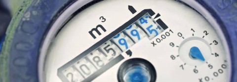
With a Level Control Panel from Cougar USA, you can monitor incoming city water pressure and receive an alarm as soon as the pressure drops, giving you time to conserve water and warn patients, tenants, and guests of the situation.

Monitor City Pressure on Fill Stations Tech Talk Transcript:

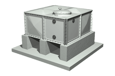
Hi I’m Tim Zacharias, with Cougar USA. In this Tech Talk, we’re going to cover Monitoring City Pressure on your fill station so when you have a flooded suction application, like in the city of Houston, where we have the code requirement to go through an atmosphere storage tank, like this before your booster pumps.

Continue reading

Low-Flow Shutdown Sequence for Pressure-Boosting Systems

Low-Flow Shutdown Sequence for Pressure-Boosting Systems

According to ASHRAE 90.1, Domestic Water Booster Systems must shut down during periods of no flow demand. Operating pump systems when there is little or no demand wastes energy and increases wear and tear on the pump and piping system. While this sounds simple, it is one of the most challenging control sequences for a Booster System.

Domestic Water Booster Systems are used to supply water to commercial buildings to be used in restrooms, kitchens, and to make up water to Hydronic Systems like Cooling Towers. The demand for water will change throughout the day and the pump system must be able to respond to these changes. In commercial office buildings, for example, there can be long periods of little or no water demand overnight when the building is empty or even in the middle of the afternoon when the building is occupied.

For a pump system to perform a low-flow shutdown, it must first be able to measure the flow demands in the system. Flow Switches and Flow Meters are mechanical means of measuring flow, which can work, but both require proper installation in the system piping for proper readings. Space and piping constraints can limit the installation of switches or flow meters.

Continue reading

Design Considerations for Water Pressure Reducing Valve (PRV) Stations in Commercial Buildings

Pressure Reducing Valve (PRV) Stations are an important component of a water-distribution system in a commercial building. The 2015 Uniform Plumbing Code Section 608.2 states that PRVs are required at any point where the system static pressure exceeds 80 PSI. Typically, this applies to mid- and high-rise buildings when the pressure boost required at the ground floor to serve the upper floors in the building is over 80 PSI. When you need to design a PRV Station, you must consider the station pressure drop, water flow, and safety devices.

To calculate the Pressure Drop across the PRV Station, we have to determine the inlet and outlet pressures. The inlet pressure is determined by the PRV location in the building. The lower the PRV is in the building, the higher the static inlet pressure will be. Typically, the PRVs are fed by a Pressure Boosting System that feeds the entire building, so the inlet pressure may also fluctuate a little, depending on the demand in the rest of the building.

The outlet pressure is determined by two factors. First is the number of floors the PRV Station is serving, and the second factor is whether the station is feeding the floors above or below the station. A good rule of thumb is that each floor will result in a pressure change of 5 PSI. If the floors fed by the PRV Station are the floors above, then you would need a higher outlet pressure at the PRV Station (around 65 to 75 PSI) because the pressure will drop about 5 PSI each floor higher in the piping. If the PRV Station is feeding the floors below, the outlet pressure would need to be lower (around 40 to 50 PSI) because the pressure will increase 5 PSI for each floor lower in the piping.

Continue reading

Break Tank Fill Valve Types – Float Versus Electronic

Many commercial buildings use storage tanks for Domestic (Potable) and Fire Water Applications, especially in Houston where it is required by Houston Amendments to the Uniform Plumbing Code Section 607. As water is used in the building, an automatic system is required to replenish the water and maintain a constant level in the tank. In domestic applications, this process can repeat multiple times an hour during peak demand loads. An automatic level-control system has two main components, Fill Valves and Controls.

Float Controlled Valves (Cla-Val model 124-01) are widely used on break tanks in commercial buildings. Float valves operate on the same principle as the valves in the back of a toilet: a float attached to a rod moves up and down with the level of the water in the tank. Float valves are simple and effective, but there are drawbacks in commercial applications. Most valves are installed on the top of tanks with the float rod directly attached to the valve, making them difficult to access and maintain. Tank-water-level adjustments are also difficult because the float rod length and float position must be changed on the valve itself.

When two float valves are used, there is no alternation between valves. The lead valve (shorter float rod) will always operate first, with the lag valve going long periods without use. This combination will eventually cause failures in both valves without proper preventative maintenance. Also, these systems typically provide little or no feedback to the Building Management System.

Continue reading

Why are Break Tanks Required in Houston for Pumping Applications?

Why are Break Tanks Required in Houston for Pumping Applications?


Some call them House Tanks, others Break Tanks, Storage Tanks, or Buffer Tanks. If you have been in the pump room of a building in Houston, you’ve seen these large water tanks, but why are they used? The Houston Amendments to the Uniform Plumbing Code Section 607 states that upstream from a pump system, an atmospheric storage tank with an air gap between the tank and city water supply must be used. This applies any time the city water pressure is insufficient to supply a building for both Domestic (potable) and Fire Water applications and the addition of pumps is required.

The City of Houston is one of a few municipalities across the country with this requirement for both Domestic and Fire Water Pumps. The tank air gap effectively separates the building’s water supply and consumption from the city water lines. This should stop any contamination from a building from getting back into the city supply and affecting others. Also, large sudden demands in a building (i.e., fire pumps) shouldn’t affect the water supply to those around it.

Continue reading

Older Domestic Booster System Modifications Versus Replacement

In Houston, there was a construction boom in the 1970s and ’80s, with hundreds of high-rise buildings adding to the skyline. Many of these buildings are still using the original mechanical systems for HVAC and pumping applications. Potential mechanical failure and energy savings are forcing building operators to choose between modifying their domestic booster system or replacing it all together.

Commercial buildings have seen a lot of changes in the last 50 years. The push for energy efficiency and a reduced carbon footprint affect everything in the building, from the exterior designs to the mechanical systems in the basement. Low-flow water fixtures, water recovery systems, and improving HVAC systems reduce water flow load profile today compared to years past.

Pressure Boosting System Design has also seen drastic changes in the same time period. Fifty years ago, large constant-speed, single-stage, centrifugal-pump systems were the design standard. These workhorses run 24/7, 365 days a year, regardless of the system demand in the building. This results in wasted energy and unnecessary wear on the pumps and piping. With smaller flow demands today, older pumps still in service are grossly oversized, making them much less energy-efficient.

Continue reading

Design Considerations for Pressure-Boosting Systems in Commercial Buildings

Design Considerations for Pressure-Boosting Systems in Commercial Buildings

More than 60 years ago, the late Dr. Roy B. Hunter developed a system for calculating water loads in commercial buildings. The estimated water demand of fixtures (water closets, sinks, etc.) is given a value called Fixture Units which have an equivalent demand load in Gallons Per Minute (GPM). The Fixture Units and Demand Load relationship is known as Hunter’s Curve and is still the basis for plumbing system design today.

Hunter’s Curve can be effectively used to calculate total system demand, but it has a glaring flaw. There is no consideration for diversity in the system demand. Using Hunter’s Curve for the basis of design of a Pressure Boosting System results in a pump system sized for all fixtures being used simultaneously, a scenario that will likely never happen. The pumps are grossly oversized for partial-demand conditions which make up 90% or more of total operation, causing poor system control and unnecessary wear on the pumps and piping system. In addition to Hunter’s Curve, Cougar USA uses field experience and data collection for system design.

To generate an accurate demand load profile, we gather as much information as possible about the building. The type of building has a huge impact on the load profile; even with similar fixture units, hospitals, hotels, schools, and office buildings will all have different load demands throughout the day and week. Special applications, the height of the building, locations of equipment, and potential future expansion are all factors in creating the right Building Load Profile. Once the system requirements are determined, we must make the right equipment selection.

Continue reading

Building Assessments for Energy Savings and System Performance Improvements

Building Assessments for Energy Savings and System Performance Improvements

In 2017, about 39% of total U.S. Energy Consumption was consumed by the residential and commercial sectors. In a commercial building, HVAC equipment (i.e., chillers, boilers, cooling towers, etc.) and lighting are the biggest targets for energy savings, but the capital costs for improving these may be prohibitive. There are many opportunities for energy savings and building performance improvements with other systems in commercial buildings.

Pumps are used in a variety of applications in commercial buildings, and 90% of them work inefficiently. There are three main reasons for pump inefficiency: pump type, size and controls. The proper combination of pump type, size and control will ensure the best system performance and lowest energy costs. Unfortunately, most pumps installed today are either improperly applied or sized and use outdated controls.

Domestic Water Pressure Boosting Pump Systems are required any time the city water pressure is too low to deliver water to a commercial building. Mid- to high-rise buildings almost always have pressure-boosting systems, and many single-story restaurants and medical facilities require high water pressure for special applications. In our experience, these systems usually suffer in all areas of inefficiency. Most are designed using fixture unit counts and maximum flow demands without looking at diversity factors and partial-usage loads. These calculations cause pumps to be oversized and incapable of performing well under partial-load conditions, which accounts for 90% or more of the total operation.

Continue reading

Pressure Boosting Systems – Pt1

Pressure Boosting Systems are essential for delivering water to high-rise buildings; however, the method for sizing these systems has not changed significantly in over 50 years!  Cougar USA’s High-Performance Design approach combines our extensive knowledge & experience with the best products on the market to deliver systems that provide constant water pressure with little to no downtime and the lowest Life Cycle Cost.  Check out this three-part Tech Talk series on Booster System Design to see how we do it.  We will cover the flow and pressure requirements of a building and pump & system selections to meet them.

Pressure Boosting Systems Design Part 1 Tech Talk Transcript:

Hi, I’m Tim Zacharias with Cougar USA on this Tech talk, this will be the first of a three-part series for sizing and selecting pressure boosting systems. On this one, we are going to be looking at the flow rate for a commercial building.

Now, a couple of different things that we need to take into account when we are looking at flow. The first place that we can start is Hunter’s curve in the fixture unit counts. This is a method that goes back to the 1960s. Basically, we can count up our fixture units in the building, look at the chart for what that says the equivalent flow rates are, and what that is going to give us is our worst-case flow rate for that building.

Continue reading

Avoiding Cavitation in Water Pressure Reducing Valves

High-rise buildings present multiple challenges for water distribution due to the high pressures required to reach the top of the building. The high pressures in the lower levels of the building cause high-pressure drops across Pressure Reducing Valves (PRVs), over 100 PSI or more, creating the potential for cavitation within the valves.

Cla-Val explains cavitation in this white paper, saying “Cavitation occurs when the velocity of the fluid at the valve seating area becomes excessive, creating a sudden, severe reduction in pressure that transforms the fluid into a vapor state, resulting in the formation of literally thousands of minute bubbles. The subsequent decrease in velocity and pressure rise that occurs after the valve seating area, when the pressurized condition resumes, causes these vapor bubbles to collapse at the rate of many times per second. Should this occur in close proximity to any metal surface, damage can take place. Over time, this can lead to valve failure.”

The damaging effects of cavitation include excessive noise, erosion of the valve and eventual valve failure. When designing a system with pressure drops greater than 100 PSI, there are two ways to avoid cavitation.

Continue reading